Assignments
Group Assignment- test runout, alignment, speeds, feeds, and toolpaths for your machine.
Week 7
According to the restrictions due to Covid-19, we had to do this group work Individually. But before that, our local insrtructor of the week, Eino Antikainen (FabAcademy 2017 graduate) gave a comprehensive tutorial on the subject, including: creating a file, setting the toolpaths and exporting it for milling, using CNC Router and safety issues. The process of CAM settings and generating the .nc file is described in the following. Here, speed value was 15000 rpm and cutting feedrate was 6000 mm/min.
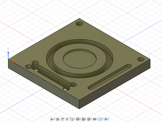
Figure 1. 3D design sample in Fusion 360
Then, we cut the board with the machine through the steps will be inclusively explained in the individual work section.
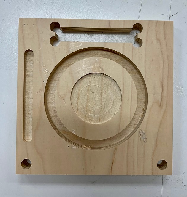
Figure 2. Cut sample with CNC router machine
After cutting the piece, I measured it with the digital calibrator.
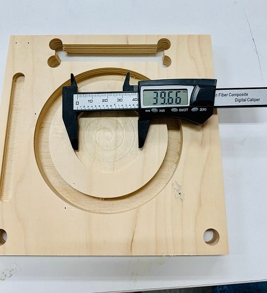
Figure 3. Measuring the sample
Table 1 shows the detailed measurements of the milled design. It can be seen from the table that the average milling length for each parameter and the target sizes of the design are quite close to their corresponding dimensions in the 3D design.
Table 1. Measurement results
| Measurement | sample size [mm] | Outer circle [mm] | Inner circle [mm] | Thickness of wood [mm] | Engraved circle thickness (smal) [mm] | Engraved circle thickness (big) [mm] | Pocket size [mm] | Pocket length [mm] |
|---|---|---|---|---|---|---|---|---|
| L1 | 150.10 | 99.13 | 80.00 | 14.69 | 2.98 | 9.87 | 4.83 | 80.35 |
| L2 | 150.02 | 99.61 | 80.05 | 14.98 | 2.80 | 9.85 | 4.92 | 80.36 | L3 | 149.95 | 99.53 | 80.13 | 14.76 | 2.91 | 9.91 | 4.85 | 80.51 |
| Average | 150.023 | 99.42 | 80.06 | 14.81 | 2.89 | 9.88 | 4.87 | 80.41 |
| Target | 150 | 100 | 80 | 15 | 3 | 10 | 5 | 80 |
For this week's assignment, we had to design something big to be built using the CNC router machine in our Fab Lab. The material available for us was Oriented Standard Board (OSB) of 11 millimeter thickness and dimension of 1197mm x 2440mm. Since the marterial is cheap and has a rough surface, it requires postprocessing to flatten the edges, but it is perfect for beginners.
Since I needed a shoe rack for my home, I decided to design simply it with three shelves. First, I measured the dimensions of the place I considered for the made shoe rack and wrote it down (90*60*30 cm^3). Then, I started with skecthing and defining dimensions in Fusion. All the slots were defined 11 mm , the same as the material thickness.
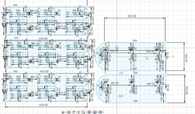
Figure 4. Sketching preparation in Fusion 360
Then, I extruded the sketch to 11 mm which is equal to the OSB thickness.
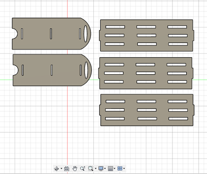
Figure 5. Exturuded components in Fusion 360
To be sure that the design will fit the OSB size, I drew a rectangle wit the same dimension of the material ( 1197mm x 2440mm) and set it as imaginary by right-click->Normal/Construction and placed all the parts over there. It is also very important to have all the parts aligned and at the same plane.
Next, to have a clue of the final product, I used Joint feature in Fusuion to assemble different parts and make a shoe rack.
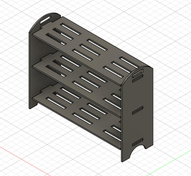
Figure 6. 3D assembly of the shoe rack in Autodesk Fusion 360
To create the tool paths (G-codes) for the CNC router, Eino Antikainen instructed us to download the post processor file and the setting files with values for different milling bits available in our Fab Lab library.
To make the G-codes in Fusion 360, first, switch from DESIGN to MANUFACTURE environment.
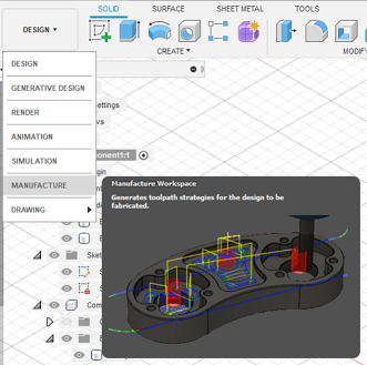
Figure 7. Changing environement to MANUFACTURE in Autodesk Fusion 360
Here are the steps to prepare the CAM settings:
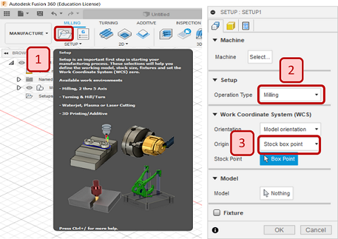
Figure 8. Setup in MANUFACTURE environement
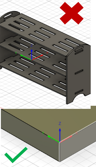
Figure 9. Setting the wrong and right work coordinated in Fusion 360
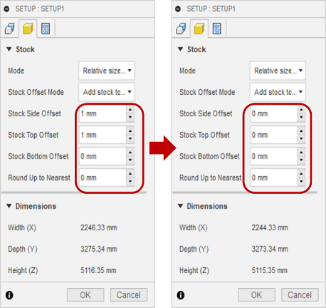
Figure 10. Setting Setting the Offset Values
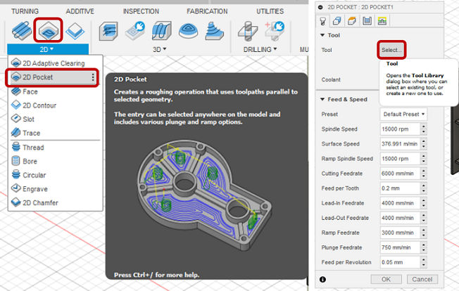
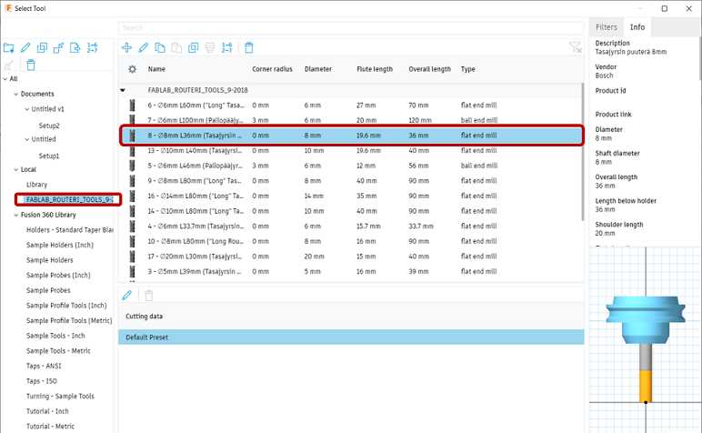
Figure 11. Setting the milling bit
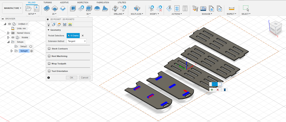
Figure 12. Setting the pockets geometry
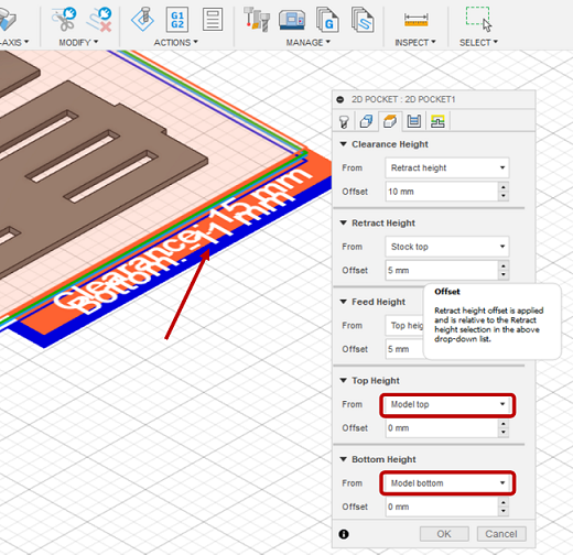
Figure 13. Setting the top and bottom heights
In the Passes tab, select Multiple Depths and set Maximum Roughing Stepdown to 3mm and select Use Even Stepdowns. Also, remeber to deselct Stock to leave.
In the Linking tab, go to Leads & Transitions and deselect Lead-In (Entry) and Lead-Out (Exit) and set the Ramp Type as Plunge.
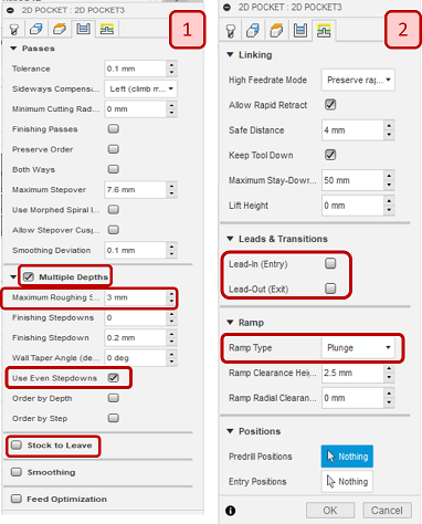
Figure 14. Passes and linking settings
The process for 2D Contour Settings is quite similar to 2D pockets settings. First, go to 2D > 2D Contour and follow the steps as shown in Figure 15.
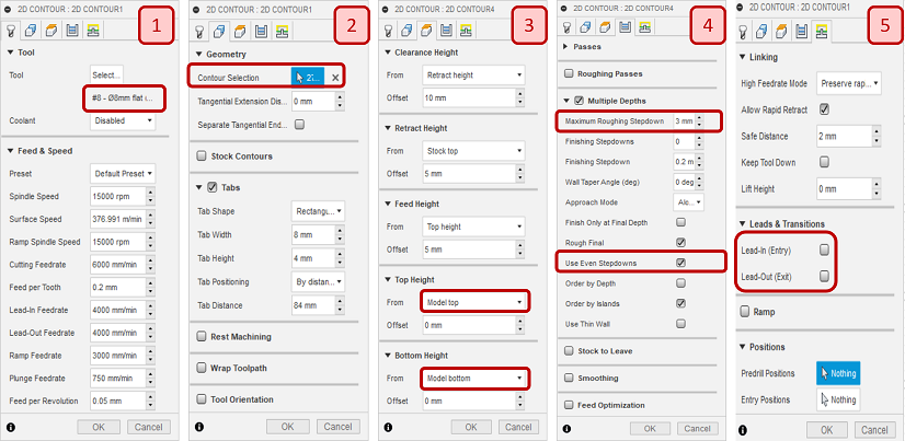
Figure 15. 2D Contour Settings
In the beginnig, I made one contour for the whole desing, but Eino suggested me to make three different contour (Figure 16) for different parts of the shape to have better control for settings.
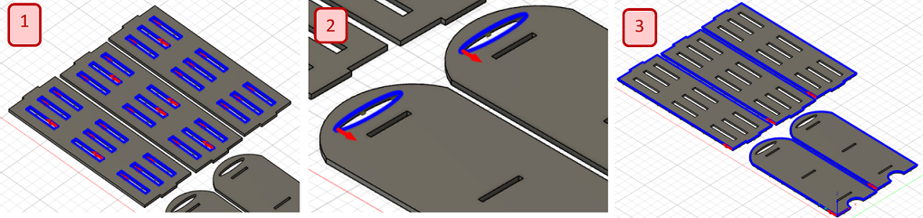
Figure 16. 2D Contour geometry selections
To keep the parts in their place and prevent moving during the milling job, I added Tabs to contour settings and dependent on the geometry, I set different distance to have enough tabs for each contour setup.
After finishing setup for pockets and contours, go to Actions, select Simulate and click on the Play icon to simulate the tool paths before exporting the .nc file for the CNC route machine, just to ensure that everything works as expected. Remember to select the setup (pocket/contour) you desired to simulate (Figure 17)
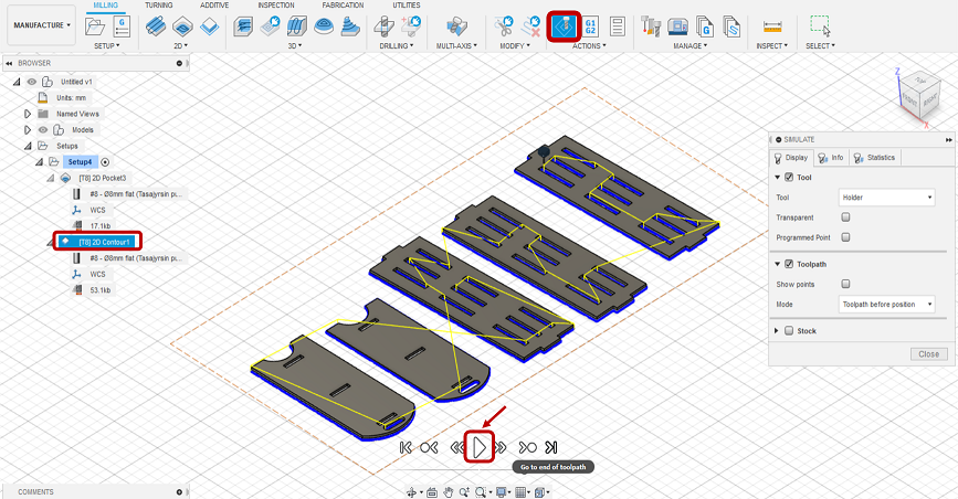
Figure 17. Simulating the tool paths
Now, you just need to create .nc file by going to Action->Generate select the right configuration (for my case, it was FabLab CNC)
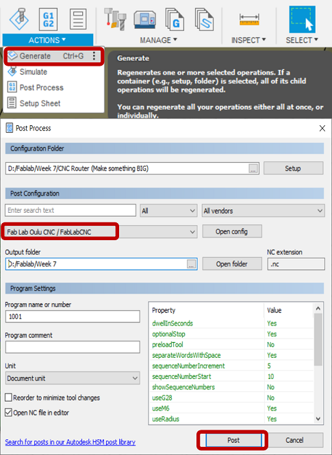
Figure 18. Generating .nc file
The CNC router in our Fab lab is Rensi E2 1325.
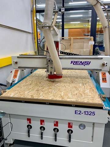
Figure 19. CNC Router Machine in Fablab Oulu
Since the milling bit, which was already installed on the machine, was not a 8mm flat one, the first step was to replace it with the right one.
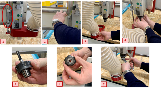
Figure 20. Changing the milling bit
Then, we should put the OSB on the machine table and screwed it tightly to make sure that it will not move during the milling process.
The CNC router machine was controlled by a computer located next to the machine. First, we should turn on the machine as shown in Figure 21.
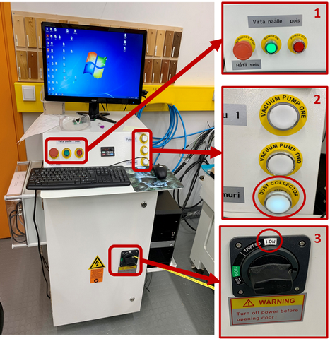
Figure 21. Starting the CNC router machine
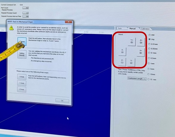
Figure 22. Starting the CNC router machine
The next step was to set the X, Y and Z origins. The header can be moved either through the software control panel. To set X and Y axes, just move the header to the desired position (X+/X- or Y+/Y-).
The same procedure can be performed for the Z axis. There is also an automatic calibration method for the Z axis. You just need to take the mobile calibrator and put it exactly underneath the milling bit (Figure 23). Next, start the calibration process from Operation > Mobile Calibration... in the software. The milling bit will move down until it touches the metal surface of the mobile calibrator, and it will automatically set the origin for the Z axis to that point.
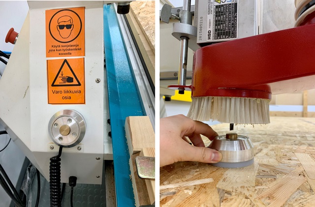
Figure 23. Adjusting the mobile calibrator
After setting the origin, I loaded the .nc file from File > open and load . Then, I clicked on Simulation to see if everything is OK. Next, the feedrate and Spindle values were reduced respectively to 80% of their maximum values, in order to increase the quality of the milling process. So, speed value would be 12000 rpm while cutting feedrate was 4800 mm/min. Finally, I pressed the play button to start the milling process.
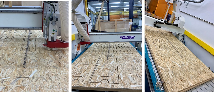
Figure 24. Milling process
This is the most difficult part for me! It took much time and energy to cut the tabs and detach the parts from the board.
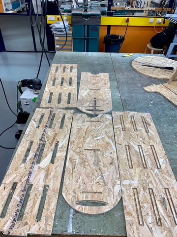
Figure 25. Assembling process
Finally, after lots of effort, I succeeded to assemble the parts.
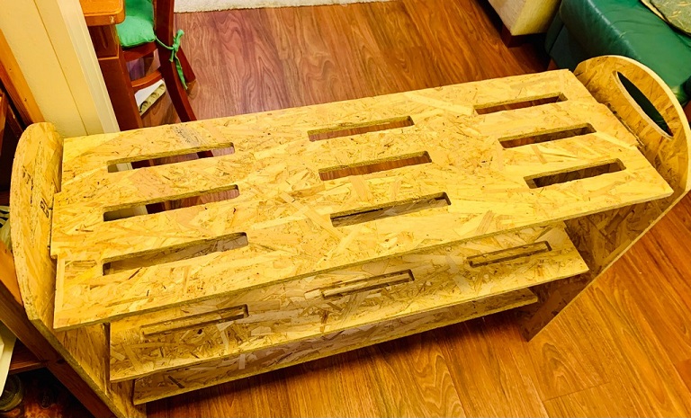
Figure 26. The final assembled shoe rack
